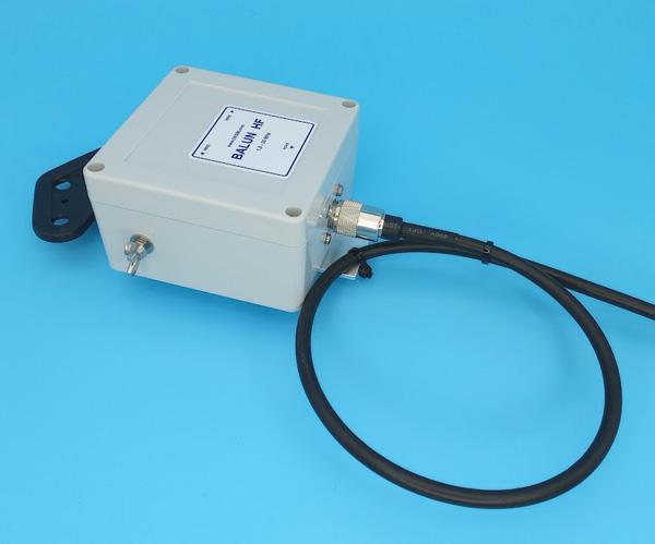
END FED 4B short mk1 1kW
Code: 399/CU 399/CU2 Choose variantRelated products
Product detailed description
END FED (EFHW) antenna.
mk1 version - mechanical version for suspension mounting
New version of the transformer component 2025
- more massive boxes, thicker walls
- brass bushings for lid screws
- Uniform box design for all models
- New power limits
- wider choice of mechanical designs
- choice of pressure valve design
- choice of Amphenol N connector
- MINI version also available in clamp mount version
- overall precision design
The radiator is single, end-fed and electrically designed in ½ lambda or multiples thereof.
It connects to the transformer circuit.
The usable bands are according to the chosen emitter.
4B short - 7-14-21-28 MHz - emitter length 12,5 m, includes coil
4B - 7-14-21-28 MHz - emitter length 20 m, does not include coil
5B short - 3,5-7-14-21-28 MHz - emitter length 24 m, includes coil
5B - 3,5-7-14-21-28 MHz - emitter length 42 m, does not include coil
Technical data:
- bands 7-28 MHz
- emitter length 12,5 m
- coil included
- antenna cable according to the selected variant
- transformer element END FED
- power load up to 1 kW PEP max (SSB 1 kW / CW 500 W / DIGI 300 W)
- Mechanical design for hanging by rope
- PL input connector (UHF)
- the antenna radiators are connected to M4 screws and secured with a wing nut
- fasteners are stainless steel
- box dimensions 105x105x90 mm
- the box is IP-65 rated
- the box is equipped with a pressure valve
- weight according to the selected variant of the antenna cable
The antenna should be supplemented with a Link Insulator, connected as close as possible to the antenna.
This will prevent shell currents and interference (RFI).
Depending on the specific mounting design, the use of an antenna tuner on some bands should be considered. The quality of the ground, surrounding objects and environment, the height of the ends of the radiator, the shape of the radiator extension (horizontal, angled, cranked, etc.) have an influence.
Optimal mounting conditions are: horizontal at 10m height, power supply with a coaxial cable of the length of the impedance repeater to the lowest band used. Impedance repeater = ½ lambda x truncation factor (for the specific cable used)
The box is supplied with a pressure valve.
Function of the pressure valve - when the instrument box is subjected to temperature changes - e.g. day/night temperature differences, or when heat is generated in the box during operation and the box cools down after operation - pressure changes and condensation of water vapour occur in the sealed box.
In some cases, a vacuum may even be created, which can cause dust and moisture to enter.
Installing a valve with a pressure balancing function is a very simple way to provide ventilation and at the same time prevent vapour condensation and dust from entering the enclosure.
Attach the coaxial cable to the transformer so that it does not hang by its own weight on the connector.

Be the first who will post an article to this item!


